LTE stands for Long Term Evolution. It is the technology that superseded GSM (2G), and UMTS (3G) as a packet switched network. The main driver by 3GPP was to consolidate its pre-decessor technologies as well as offer faster data rates to enhance user experience. Thus initial requirements for peak data rates were 100Mbps in DL and 50Mbps in UL with low latency of 10-20ms. In summary LTE was developed to:
Simplify the RAN (removing the UMTS RNC and replacing with e-nodeB as well as MME)
Increase throughput (with features like MIMO and HARQ)
Reduce Latency
Improve spectrum efficiency
Provide frequency flexibility (thus scalable form 1.4 to 20 MHz)
Improve terminal power efficiency
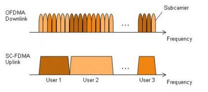
The multiple access technique utilized is OFDM (Orthogonal Frequency Division Multiplex) in the downlink and SC-FDMA (Single Carrier - Frequency Division Multiple Access) in the uplink. This modulation technique allows for many subcarriers to be close together, hence making the system robust to interference as well as improving spectral efficiency. As a result, more data can be sent in the same frequency bandwidth - which also translates to faster data rates. OFDMA supports various modulation schemes from BPSK, QPSK, 16QAM to 64QAM. Peak to Average Power Ratio is a main challenge of OFDM, thus in the uplink SC-FDMA is utilized.
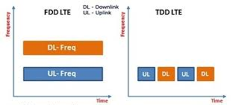
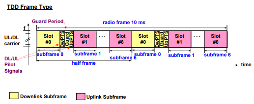
There are two ways in which LTE can operate. It can operate in either the frequency or time domain as FDD and TDD.
•LTE FDD (Frequency Division Duplex) requires two separate wireless communication channels on separate frequencies, one for transmit and the other for received data
•LTE TDD (Time Division Duplex) TDD uses a single frequency band for both transmit and receive. Then it shares that band by assigning alternating time slots to transmit and receive operations
The diagram below helps illustrate the differences.
LTE AIR INTERFACE
The basic EUTRAN radio frame is 10ms long - and is divided into 20 slots with each one being 0.5ms long. The two slots form a subframe 1ms long - and is the smallest time unit the scheduler assigns to physical channels. In FDD, there is a time offset between downlink and downlink transmission
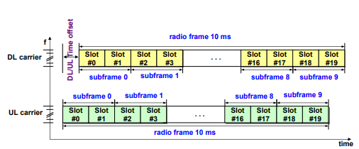
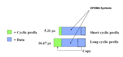
Furthermore, each slot is divided into 7 OFDM symbols (depending on choice of Cyclic Prefix). If it is a short cyclic prefix then 7 symbols are used. If it is a long cyclic prefix, 6 symbols are used.
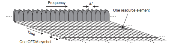
Thus, as a unit, each RB is made up of 12 OFDM subcarriers and 7 OFDM symbols, with each subcarrier having bandwidth of 15 KHz, giving us total bandwidth of 180 KHz per RB.
UE Categories

Other Key Configurations | Description |
|---|---|
Duplexing | FDD, TDD, Half duplex FDD |
Channel Coding | Turbo Code |
Channel Bandwidth (# of subcarriers) | 1.4(72), 3(198), 5(330), 10(660), 15(990),20(1320) |
Transmission Bandwidth Configuration NRB : (1 resource block = 180kHz in 1ms TTI=Transmission Time Interval ) | 6, 15, 25, 50, 75, 100 |
Modulation Schemes | UL: QPSK, 16QAM, 64QAM(optional) DL: QPSK, 16QAM, 64QAM |
Multiple Access Schemes | UL: SC-FDMA (Single Carrier Frequency Division Multiple Access) supports 50Mbps+ (20MHz spectrum) DL: OFDM (Orthogonal Frequency Division Multiple Access) supports 100Mbps+ (20MHz spectrum) |
Peak data rate in LTE | UL: 75Mbps(20MHz bandwidth) DL: 150Mbps(UE Category 4, 2x2 MIMO, 20MHz bandwidth) DL: 300Mbps(UE category 5, 4x4 MIMO, 20MHz bandwidth) |
Some Parameters | Physical Cell identifier (PCI), RSRP (Reference Signal Received Power), RSRQ (Reference Signal Received Quality) |
Uplink Channels | PUSCH: Physical uplink shared channel PUCCH: Physical Uplink Control Channel PRACH: Physical Random Access Channel |
Downlink Channels | PBCH: Physical Broadcast Channel PCFICH: Physical Control Format Indicator Channel PHICH: Physical Indicator Channel PDCCH: Physical Downlink Control Channel PDSCH: Physical Downlink Shared Channel |
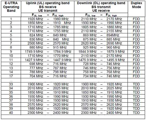
Operating Bands