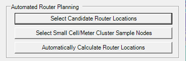
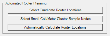
The purpose of automated router planning within the Mesh Module is to evaluate potential sites quickly and efficiently and without the need to do it manually. Once you have defined your meters and meter types, you may go into the automated router planning.
Your first option will be to select candidate router locations.
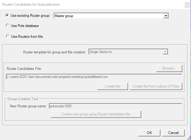
You may choose an existing router group by selecting from the drop down button
You may choose a pole database which is defined under the menu Databases>Towers/poles
You may choose routers from file where you may browse for an existing router candidate file. You may create a router candidate file on your own with a bounding polygon(BNA) and potentially a street directory also. You also have the option to create a router candidate file from a subset of poles. You may select the appropriate BNA and configure your router candidate selection options.
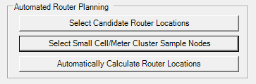
The next selection is Select small cell/meter cluster nodes:
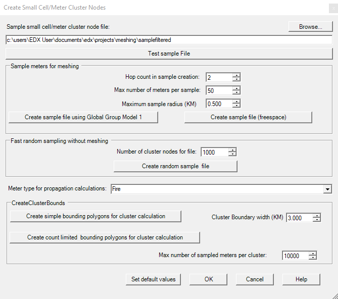
You may browse and test a previously existing sample file.
You may create a sample file for meshing using either Global Group Model 1, which is set in the prop model dialogue, or only using free space as the propagation choice to create a sample file. ****yes please** a simple explanation is fine
You may choose to create a fast random sample file without meshing
You may also create cluster bounding polygons for cluster calculation.
The last selection is to Automatically calculate router locations:
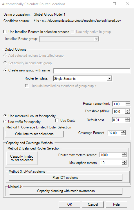
The “Use installed Routers in selection process” will take previously created sites and assume that they are already active. This option will look to improve coverage by adding addition sites to the existing active sites.
You must give a new group name and choose the template you wish to use for the routers.
The options within the middle allow you to set your router range and signal level target. The options you select will be used in whichever method you choose.
Method 4 is recommended because it pre-calculates the mesh network and tries to connect the mesh nodes together. **** Method 4 is recommended because *********
When selecting method 4 you are presented with this dialogue:
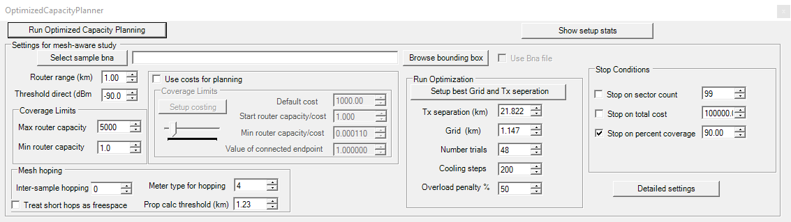
The router range and signal level threshold are carried over from the previous menu.
You may set the coverage limits and mesh hopping options. Max router capacity is how many meters a router can serve. Min router capacity is how many meters must be served by a router to be considered for placement. *** rephrase
The “Use costs for planning” checkbox will take into account the costs of the design.*** RE-phrase - put into advanced article -
You may manually optimize the run and set each option to your desired. The “setup best grid and tx separation” will adjust these settings for you.
You would browse for a BNA file using “Browse bounding box” if you wanted to place routers within a given area of interest.
Once you select Run Optimized Capacity Planning you are presented with a new window that will display the useful routers found and the subscribers they serve. It will display how many routers were found and what percent coverage they provide.
You can also choose to add in additional routers at Candidate Router/Hub locations with the “+add” button. When the “+add” button is turned on, you can simply click on the candidate router/hub locations to add new sites and see the subscriber units they serve.
You can toggle routers active and inactive with the “X toggle” button. With the “X toggle” button turned on, you can click on a router turn it inactive and adjust the design. Click back on the router to turn it back to active.
When the router locations are acceptable, click “Yes” at the bottom of the window to accept the new routers and the created transmitter group. You may also click “No” to reject the candidate routers and go back to the Optimized Capacity Planner and make adjustments.