...
Create a graphic layer by tracing the building on the map
Navigate to Draw>draw building in the menu bar
Select the building height and the material type.
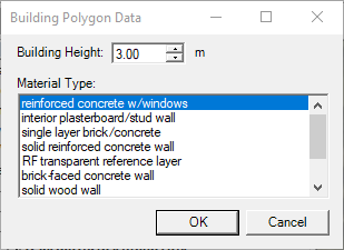
Click okay.
Trace the outside of the buildings by clicking down on the map around the perimeter of the building. Once you are back to your starting point you will double click on the starting point to close the shape.
Continue this process for all of the buildings you would like to include in our project.
After all the buildings have been traced, right click on the outline of one of the buildings and choose the option save to file.
Name the file and save as an MCS file.
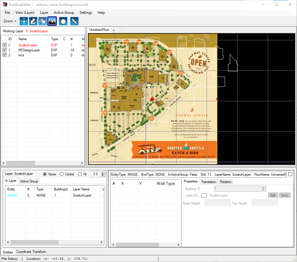
Open the building editor by selecting the building editor button on the button bar.
Import your MCS file by going to File>Import from MCS>Create new project
Select the file you just named.
Once you have your MCS file selected this dialogue box will appear.

You can select the edit material color button and select the colors you would like to use for each material type. Once your material colors have been selected click okay and return back to the building editor dialogue box.
The image overlay feature allows you to overlay the image file, use the coordinate transform tools to rotate, scale , and move the image to line up with the building outline.
Select file>image overlay>load and select the image file of your building layout.
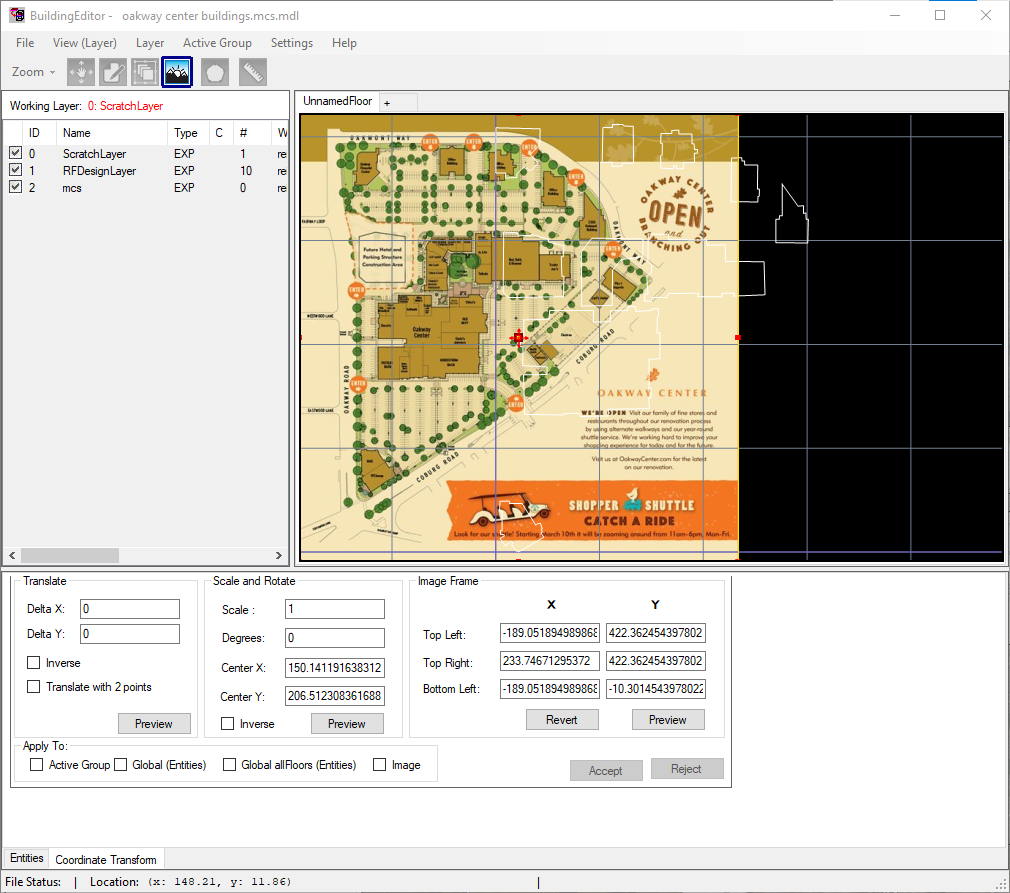
Align the image with the building outline by selecting the coordinate transform tab.
Check the box translate with two points and the box for image .
Select one point on the image and the and the correlating point on the building outline. Then select preview and the image will shift to line up with the building outline.
To change the image size to better align with the building outline, scale the image by changing the number in the scale box to 0.9 and then click preview. You will see the image zoom out. To zoom in check the box for inverse and select preview until the image aligns with the building outline.
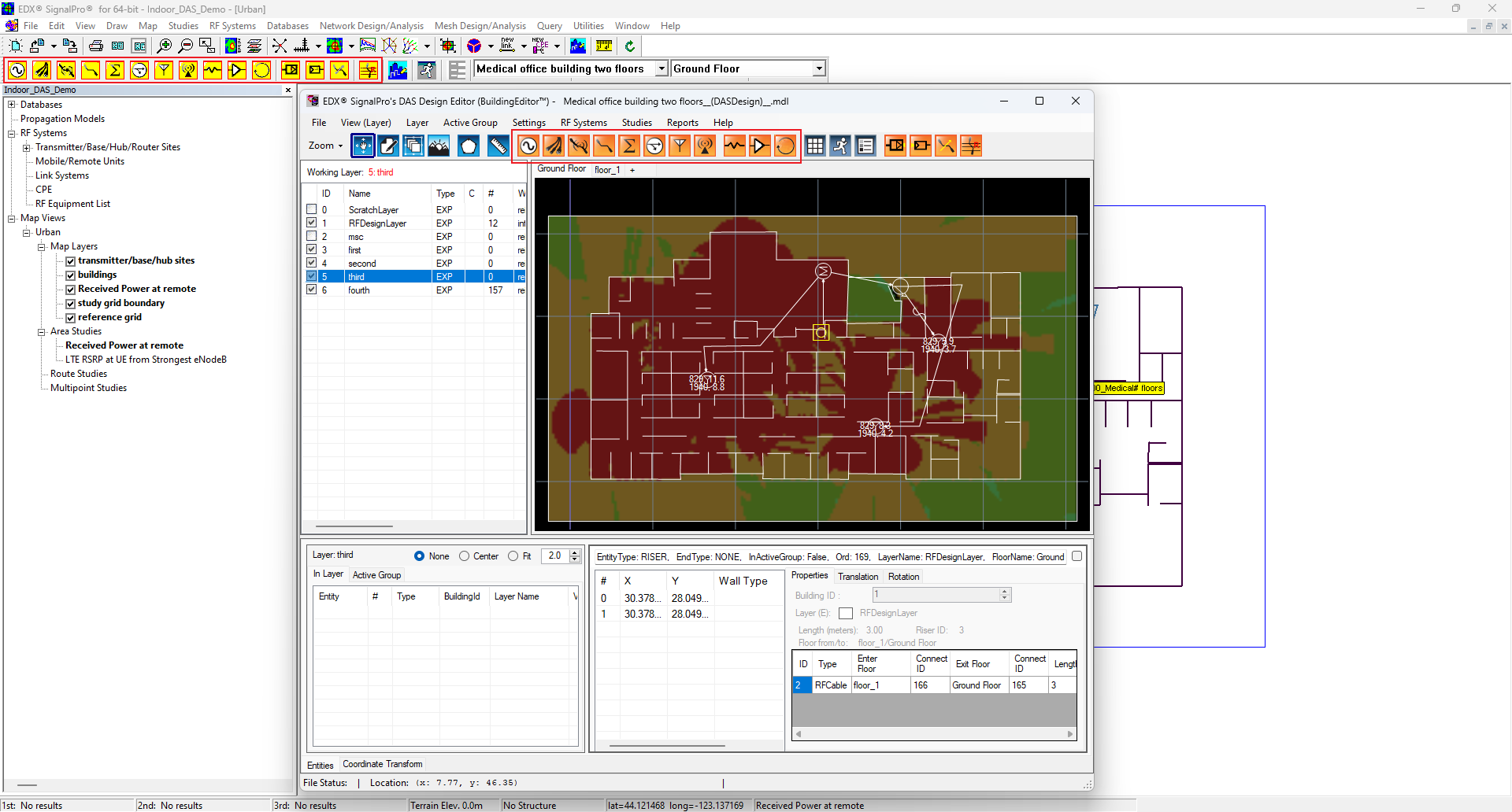
Draw the interior walls.
Navigate to the entities tab and select draw polygon.
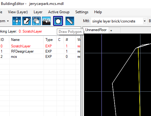
You will see a drop down for material type. Select your material type.
Draw the interior walls by clicking once where you want the wall to start and twice where you would like the wall to end.
When drawing your walls you can go back and forth between the coordinate transform tab and the entities tab to align the image as you work.
Once all of the interior walls have been drawn navigate to file>save as>name your file>then save it as an MDL file
Exit the building editor.
Navigate to databases>buildings/floor plans in the menu bar.
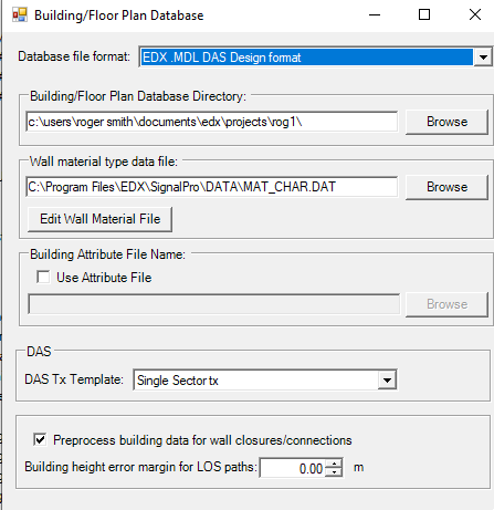
Change the database file format to be MDL.
Set the building/ floor plan database directory to the location on your computer you saved your MDL file.
Click okay back to the main screen.
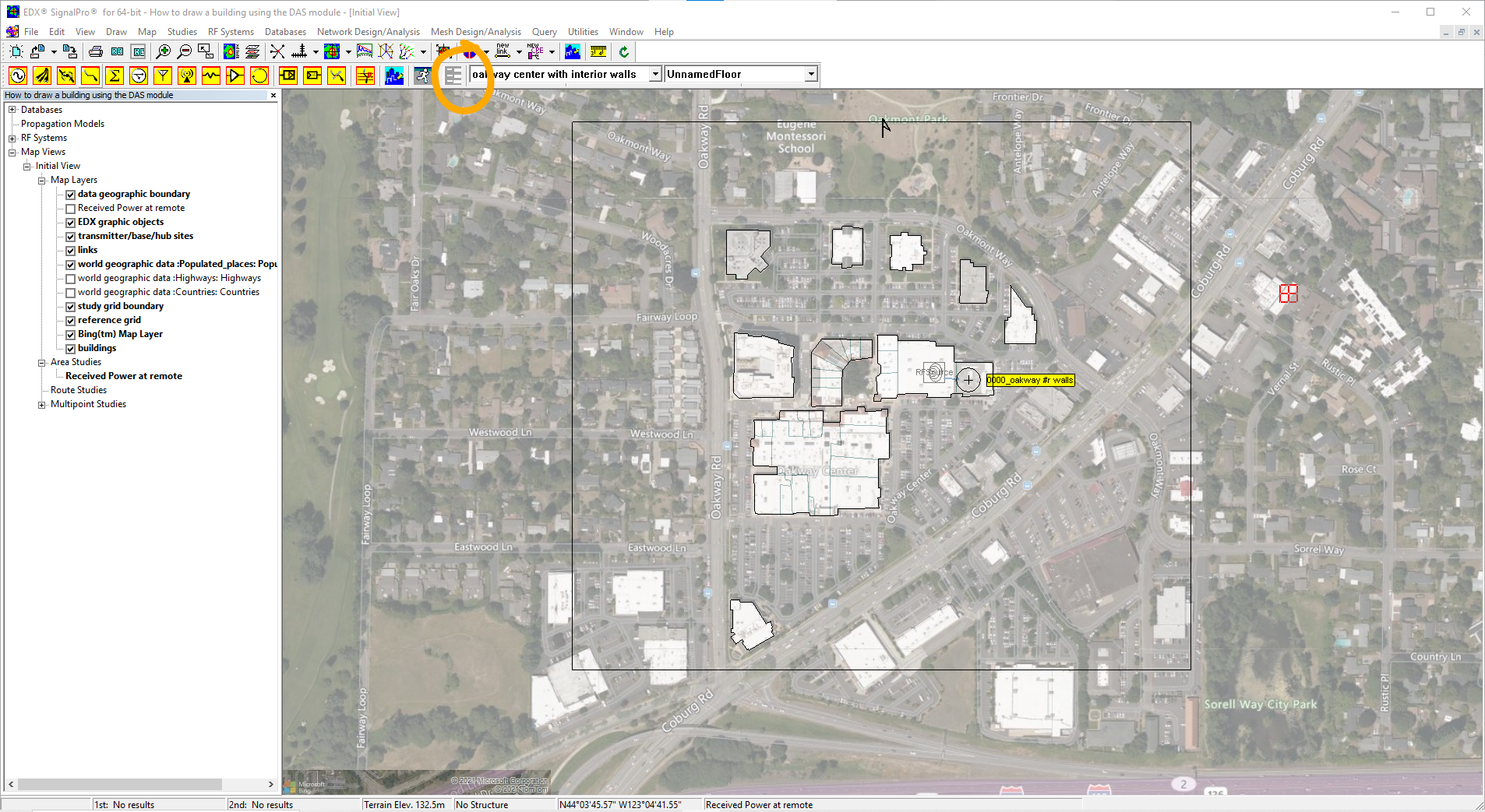
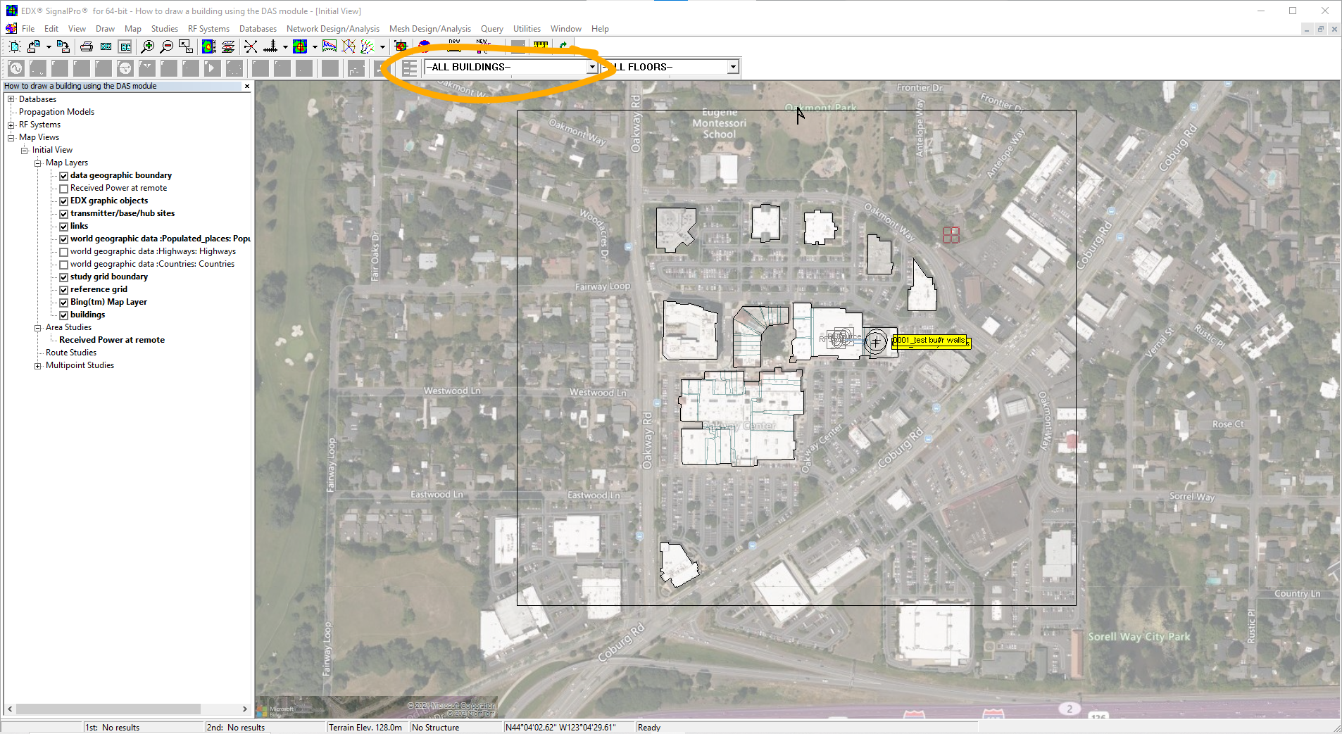
You will now see the DAS module toolbar appear at the top of your screen. In the first drop down box select the MDL file you wish to use.
Choosing Choose the equipment and setting the parameters settings of the study you will want to run.
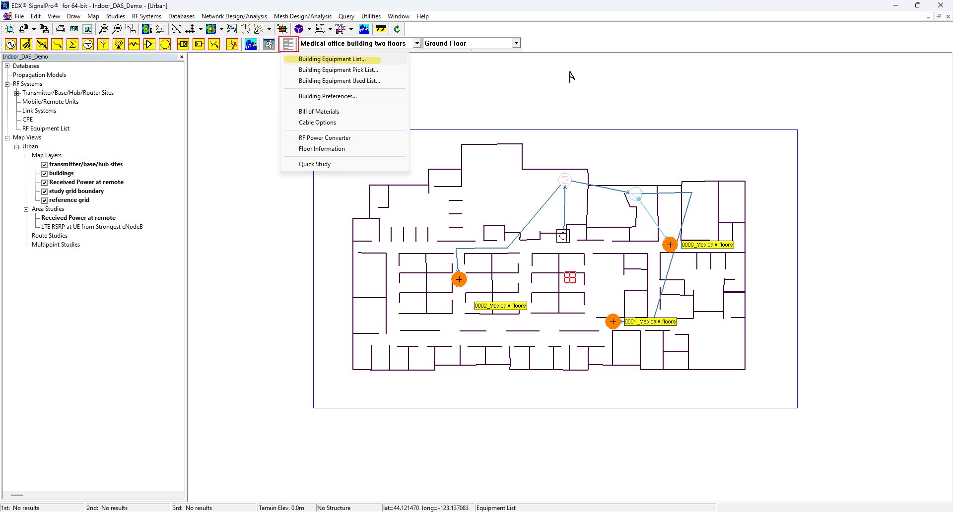
To select your equipment select the option for building equipment list in the button bar.
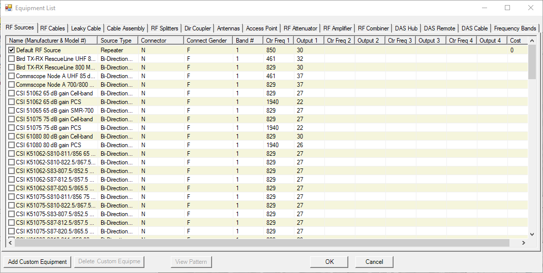
Once your equipment has been selected click okay.
Set up your mobile/ remote unit by navigating to RF systems>mobile/ remote unit in the menu bar.
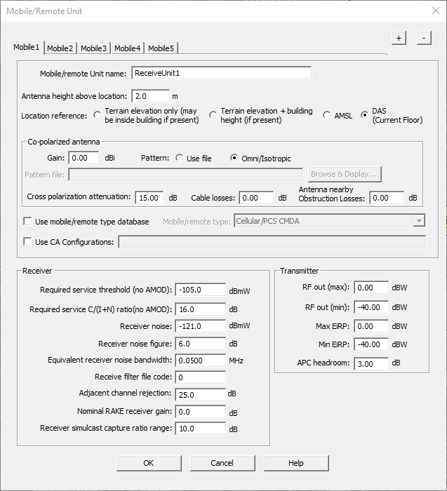
Under the section for location select the option DAS (current floor).
Click okay.
Set the propagation model. Navigate to studies>propagation models in the menu bar.
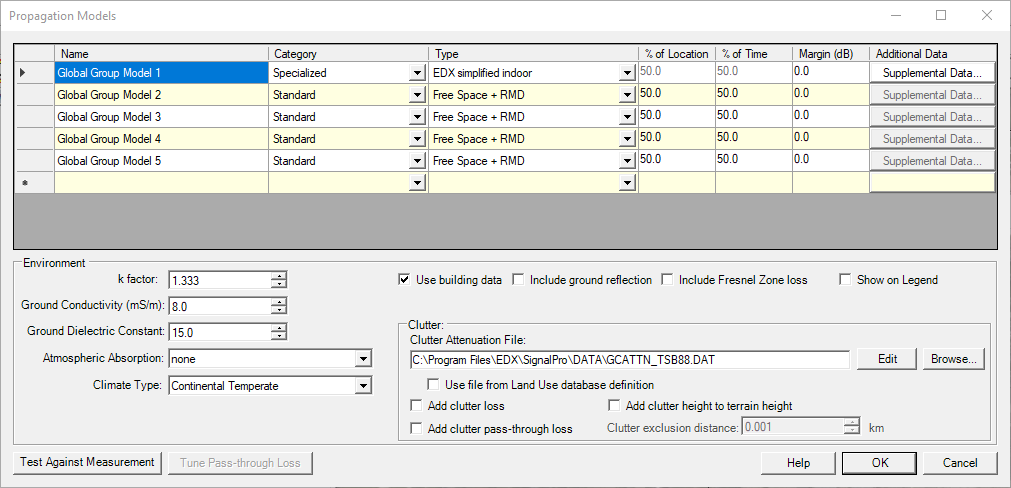
Change the category to specialized and the type to EDX Simplified Indoor.
Check the box for use building data.
Press okay.
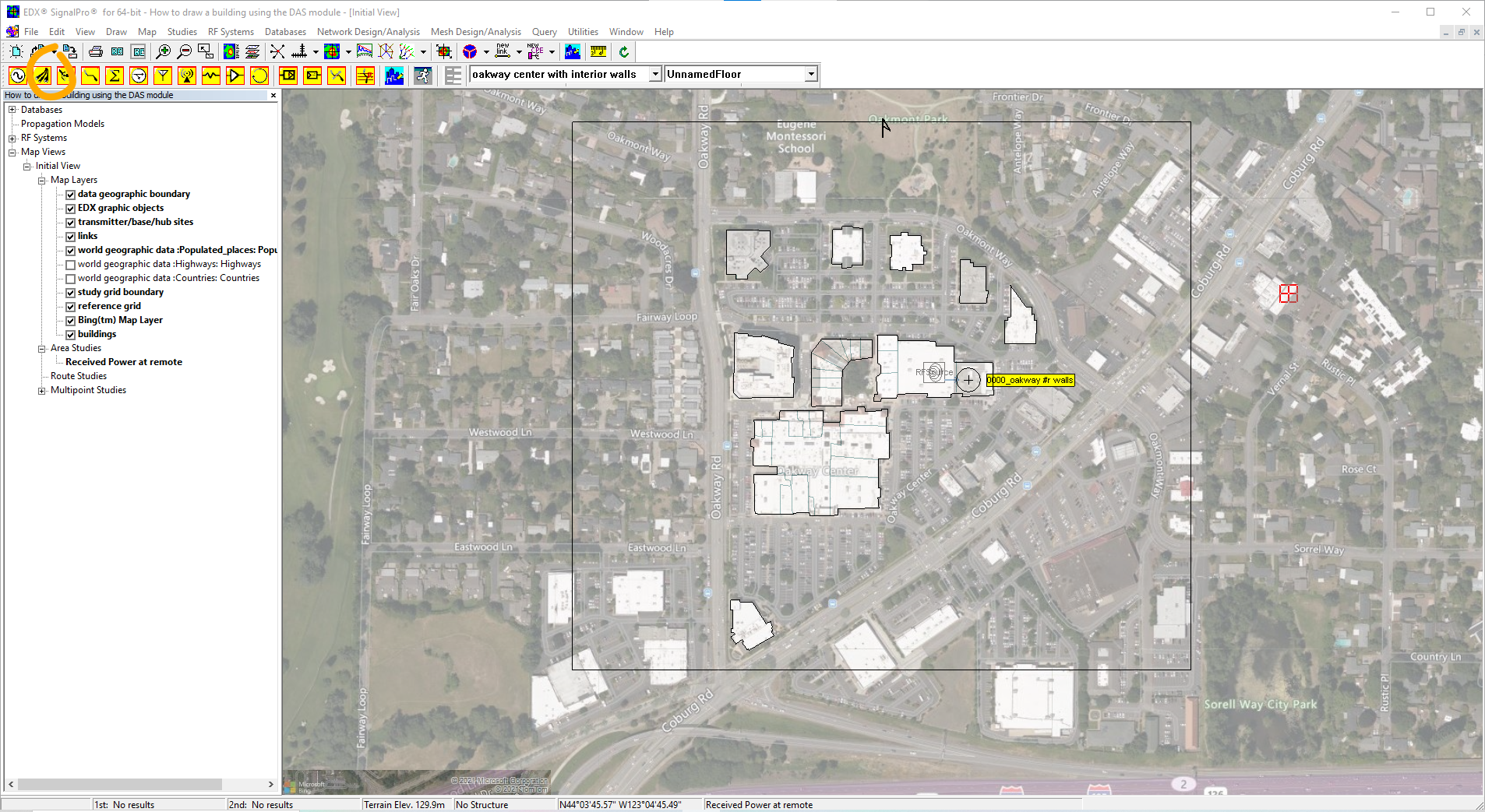
Set the study grid area and point spacing. Navigate the define study grid button in the button bar.

Click down once to start drawing the study grid area and then click down a second time to end the box.
To set the study grid point spacing navigate to studies> define study grid in the menu bar.
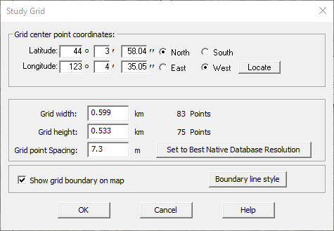
Study point spacing should be high enough to give optimal results.
Please note: If the study point spacing is too low the study may show vague results. We recommend setting grid point spacing to a number that produces approximately one thousand points for the grid height and width. The grid point spacing is dependent on the dimensions of the study grid.
Click okay.
Set up your area study. Navigate to studies>area studies in the menu bar.
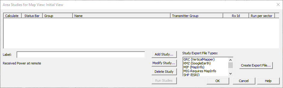
Select add study.
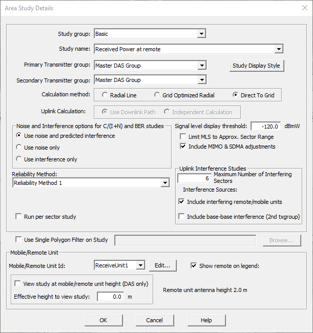
Select master das group Master DAS Group for the first and second transmitter group drop downs.
For calculation method select direct to grid.
Click okay and return back to the main screen.
Place our the RF source and antenna by selecting them in the button bar and placing them down on the map.
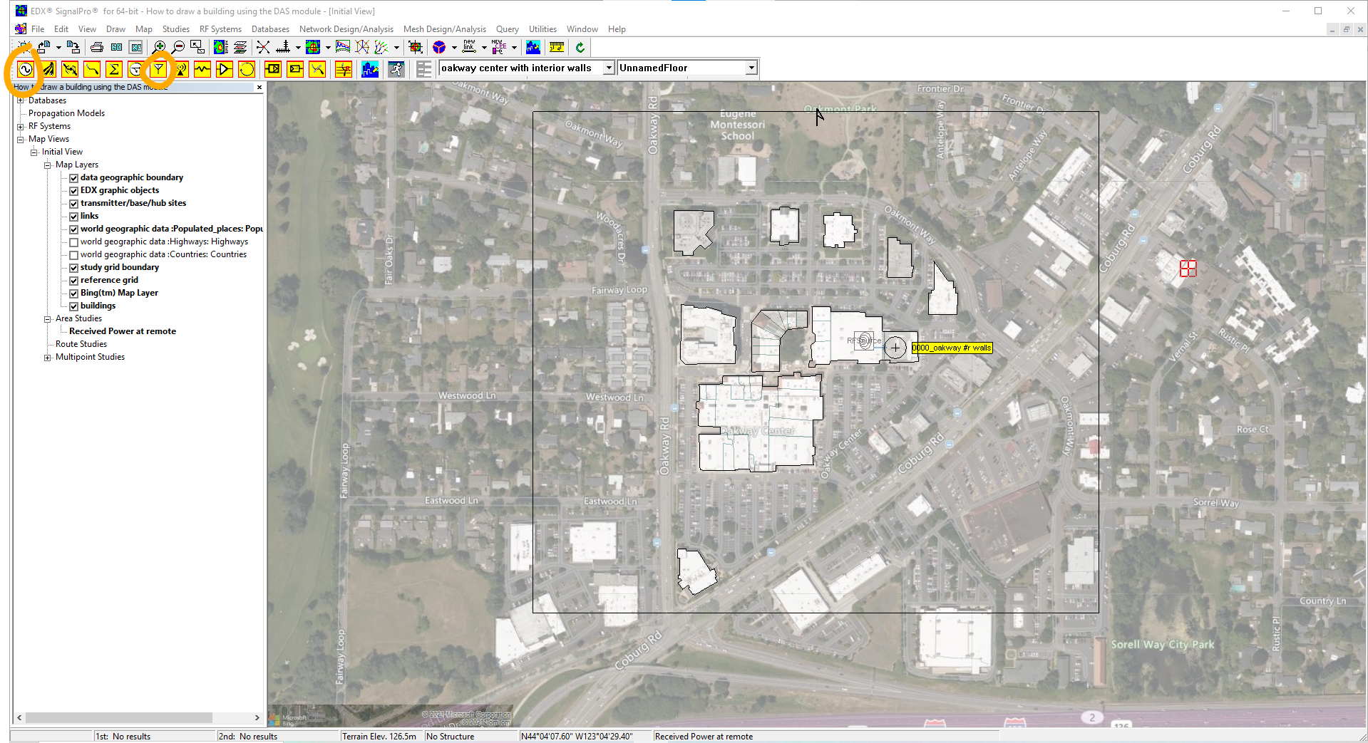
Place the RF cable select the RF cable button in the button bar.
Click once on the RF source and then double click on the antenna.
Now you are ready to run the study.
...