...
EDX SignalPro has the capability of tuning your propagation model. Model tuning is one of the final steps a user could take to more accurately represent what is going on in the real world and complete or finish their design. Model tuning is the process of taking real life measurement drive test data and comparing that with predictions in SignalPro. The user takes these comparisons and is given a suggested new best fit loss for each associated clutter category. This new loss is meant to be the most accurate representation of your clutter attenuation values based on the users drive test data, or what's in the real world. A user would want to do this so that they can more accurately design a live or potential RF system/design.
The user must first obtain valid measurement drive test data. This is done by capturing RSSI values with a reader scanner while driving through the real worlda predetermined drive test route with the appropriate setup. This drive test data is mostly contained to roads/ streets but the idea is to also capture other potential clutter categories as well to help you more accurately represent the real world in your design. One route should include a variety of areas of different morphologies around the site to allow for varying RF conditions to be captured. This will help for losses to be more accurately represented in the propagation model, which in turn will reflect as close as possible of a real world scenario in your RF design. Once the drive test data is recorded the user will need to construct a new file to containing the that measurement data. This file is a can be created in the specific EDX measurement data format. You can read more about this format from this articlehere: Creating Measurement/Drive Test Files for EDX
There are two options for model tuning within SignalPro. Both can be found from within the Propagation Models menu. The two options are called Test Against Measurement and Tune Pass-through Loss, they are highlighted in the image below:
...
Test Against Measurement: This option only applies if the user has the “Add Clutter Loss” checkbox switched on/active. Press the test against measurement button to bring up this dialogue:
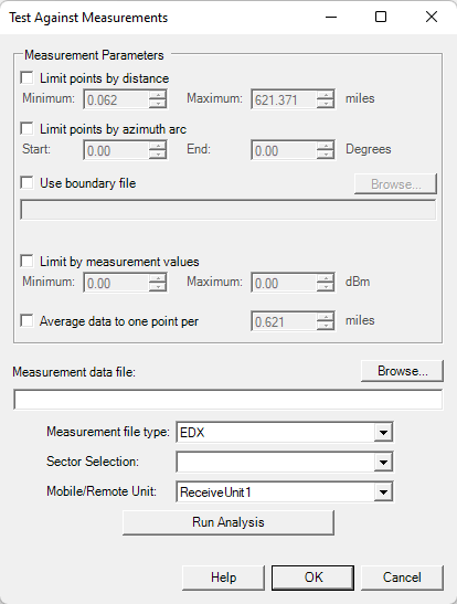
From here you will press “Browse…” to point to your properly formatted measurement drive test data file. The measurement file type may be left as EDX, because if that is the format we you have assembled our your measurement data in. You will want to select the appropriate sector and mobile/remote unit. Its important to note just in case missed, the EDX measurement drive test data format is specific to a single sector only. Then you can press run Run Analysis where you will be presented with the Measured vs Predicted dialogue box:
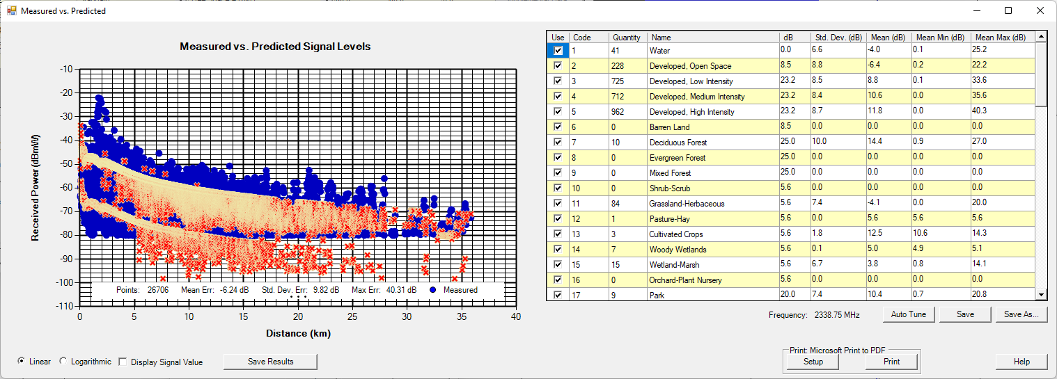

Please note that these values are not relevant. This measurement data was fabricated for the purpose of this article. Froom From here you can select or deselect the various categories you want to tune and you can press the “Auto Tune” button to do so. This will adjust the loss value for the clutter categories selected so that they more accurately represent the drive test data. You will want to press “Save As..” to make a new copy of the original clutter attenuation file being used. You can then use this new clutter attenuation file with the edited loss values within your project.
2. Tune Pass-Through Loss: This option for model tuning only applies when the user has the “Add Clutter Pass-Through Loss” option check on/active from within the propagation models menu. You will only be able to tune your model if this option is selected, you cannot have both add clutter loss and clutter pass through loss selected. The measurement file format will still be the same. When pressing the Tune Pass-Through Loss button you are presented with a new menudialogue box:
...
First you will want to look in the “Details” section and be sure to set your sample spacing for pathloss prediction similar to the clutter resolution being used in the project. Similarly to Test Against Measurement, you will then press choose data file to browse for your properly formatted measurement drive test data file. You will select the appropriate sector under the “Using Transmitter:” drop down menu. You will also select your mobile unit/receiver just below that. It is important to note the section below labeled Details. You will want to be sure to pay attention to this sectionThen similarly to Test Against Measurement, you will press choose data file to browse for your properly formatted measurement drive test data file. Once you select your appropriate measurement file the menu will begin to load the data. This can take a few moments. Once the file has been loaded the menu should populate something similar to this:
...
Again, similar to test against measurement, this is specific to one sector at a time. You can go through and select which clutter categories you do and do not want to tune. When you are ready to tune a clutter category you will press the Tune Pass-through Clutter Loss button. You will want to press “Save As” to save a copy of the edited clutter attenuation file. You may then utilize this edited clutter attenuation file within your design.
...